 After some crunch time at work and a bit of vacation it's about time to continue with my "me too" attempts at using tessellation. Before proceeding with my terrain implementation I'd first like to give a bit of information about the new tessellation functionality in OpenGL. Again, the usual disclaimer: I'm just learning that stuff as well, so this will be basic explanations.
Introduction
Together with the subsequent geometry shader, tessellation is one of the stages where vertices can be created (or discarded). It operates on patches, i.e. sets of vertices (usually triangles or quads). When the application issues the draw call, it can specify the patch size, e.g. by calling
glPatchParameteri(GL_PATCH_VERTICES, 3);
This informs OpenGL that three subsequent vertices are to be considered a patch. The tessellation shader then subdivides the patch into additional triangles. Leadwerks currently only uses triangle tessellation, so that's what I'll consider here, but especially quad tessellation (patches of size four) is of interest as well (suggestion filed).
An OpenGL4 tessellation shader actually consists of three separate stages (as in DirectX11, by the way), one fixed and two programmable:
- The first (programmable) stage is the tessellation control shader. Its main job is to specify the tessellation factors, ie how often the patch should be subdivided.
- The second (fixed) stage actually creates the additional vertices.
- The third (programmable) stage, the evaluation shader, provides the opportunity to process the vertices and their attributes before they are passed to the fragment stage.
Variable names
Before actually using the tessellation shader for anything meaningful, I'd first like to describe a pass-through shader: a tessellation stage that actually does nothing (apart from using up valuable resources...). In principle, the vertex and fragment shaders can be left as is when adding a tessellation shader. However, care must be taken with the variable names for data that is passed between stages. For example, a typical Leadwerks vertex shader might have the following input:
in vec4 vertex_color;
in vec2 vertex_texcoords0;
and the corresponding output
out vec4 vColor;
out vec2 vTexCoords0;
which is passed to the fragment shader by name
in vec2 vTexCoords0;
in vec4 vColor;
Now, if you put in a tessellation shader, vColor and vTexCoords0 will be passed into the control shader, and you can't directly write back to those variables. So, you might have an intermediate variable pair
out vec2 cTexCoords0[];
out vec4 cColor[];
(those are arrays because the control shader operates on the whole patch) and then in the evaluation shader define
//Inputs
in vec2 cTexCoords0[];
in vec4 cColor[];
//Outputs
out vec2 vTexCoords0;
out vec4 vColor;
so you're back to the original variable names that the fragment shader expects. By the way, there is one thing you might want to change in the vertex shader: You usually pass vertices in world space to the tessellation, not camera space. So, instead of the usual
gl_Position = projectioncameramatrix * ex_vertexposition;
in the vertex shader, you would rather do a simple
gl_Position = ex_vertexposition;
and do the vertex transformation later on in the evaluation shader.
Control shader
The tessellation control shader starts with a layout definition
layout(vertices = 3) out;
This defines the size of the patch that is submitted to the tessellation stage. While you will normally find a value of three here, it doesn't have to be that way - you could define a patch size of four and fill in the data for the missing vertex right in the control shader.
Now, since we're heading for a pass-through shader, the vertex attributes should be handed down to the next stage unmodified:
cTexCoords0[gl_InvocationID] = vTexCoords0[gl_InvocationID];
cColor[gl_InvocationID] = vColor[gl_InvocationID];
and so on for the other interpolators. This needs a bit of explanation: First, as mentioned, the control shader has access to the whole patch data, so the attributes are defined as arrays rather than single values. Since the patch size is three, cColor[] for example will have the values cColor[0], cColor[1] and cColor[2], storing the colors for all three patch vertices. The control shader is executed once per vertex in the patch (before everything is passed to the next stage), and the predefined variable gl_InvocationID gives the current execution count (so it runs from 0 to 2).
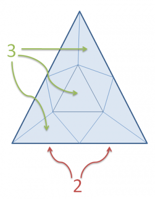
Now to the most important thing in the control stage: defining values for gl_TessLevelInner[] and gl_TessLevelOuter[] - the tessellation factors. They define how often the patch's edge (gl_TessLevelOuter) and interior (gl_TessLevelInner) should be subdivided. It depends on the patch type (triangle, quad) how many tessellation factors there are; for a triangle, there are one inner factor and three outer ones. I guess a picture is worth a thousand words:
In this image, the triangle has an inner tessellation factor gl_TessLevelInner[0] of 3 (you need three small triangle to cross the large one), while glTessLevelOuter[0], glTessLevelOuter[1] and glTessLevelOuter[2] are all 2 (every edge is divided into two segments). Now, for a pass-through shader all tessellation factors should be equal to one, leaving the original trangle unharmed:
if (gl_InvocationID==0)
{
gl_TessLevelInner[0] = 1.0;

gl_TessLevelOuter[0] = 1.0;
gl_TessLevelOuter[1] = 1.0;
gl_TessLevelOuter[2] = 1.0;
}
The if statement in the beginning makes sure that we calculate those factors only once for the patch (remember: the whole control shader is executed for every vertex in the patch).
And that's it for the (pass-through) control shader! This definition will then be send to the fixed tessellation stage which takes your recipe and creates many shiny new triangles (or in our case: not). Next time I'll go from there and describe the evaluation shader. So long!
By the way: The title image is one of my hasty smartphone snapshots taken while going cycling on the Isle of Mallorca. This is the road to Sa Calobra, steeply winding down to the sea where you can relax in one of those nice cafés - after which you unfortunately have to ride back up again...
-
 8
8


6 Comments
Recommended Comments