Vulkan Tessellation Made Practical
Now that I have all the Vulkan knowledge I need, and most work is being done with GLSL shader code, development is moving faster. Before starting voxel ray tracing, another hard problem, I decided to work one some *relatively* easier things for a few days. I want tessellation to be an every day feature in the new engine, so I decided to work out a useful implementation of it.
While there are a ton of examples out there showing how to split a triangle up into smaller triangles, useful discussion and techniques of in-game tessellation is much more rare. I think this is because there are several problems to solve before this technical feature can really be made practical.
Tessellation Level
The first problem is deciding how much to tessellate an object. Tessellation should use a single detail level per set of primitives being drawn. The reason for this is that cracks will appear when you apply displacement if you try to use a different tessellation level for each polygon. I solved this with some per-mesh setting for tessellation parameters.
Note: In Leadwerks Game Engine, a model is an entity with one or more surfaces. Each surface has a vertex array, indice array, and a material. In Turbo Game Engine, a model contains one of more LODs, and each LOD can have one or more meshes. A mesh object in Turbo is like a surface object in Leadwerks.
We are not used to per-mesh settings. In fact, the material is the only parameter meshes contained other than vertex or indice data. But for tessellation parameters, that is exactly what we need, because the density of the mesh polygons gives us an idea of how detailed the tessellation should be. This command has been added:
void Mesh::SetTessellation(const float detail, const float nearrange, const float farrange)
Here are what the parameters do:
- detail: the higher the detail, the more the polygons are split up. Default is 16.
- nearrange: the distance below which tessellation stops increasing. Default is 1.0 meters.
- farrange: the distance below which tessellation starts increasing. Default is 20.0 meters.
This command gives you the ability to set properties that will give a roughly equal distribution of polygons in screen space. For convenience, a similar command has been added to the model class, which will apply the settings to all meshes in the model.
Surface Displacement
Another problem is culling offscreen polygons so the GPU doesn't have to process millions of extra vertices. I solved this by testing if all control vertices lie outside one edge of the camera frustum. (This is not the same as testing if any control point is inside the camera frustum, as I have seen suggested elsewhere. The latter will cause problems because it is still possible for a triangle to be visible even if all its corners are outside the view.) To account for displacement, I also tested the same vertices with maximum displacement applied.
To control the amount of displacement, a scale property has been added to the displacementTexture object scheme:
"displacementTexture":
{
	"file": "./harshbricks-height5-16.png",
	"scale": 0.05
}
A Boolean value called "tessellation" has also been added to the JSON material scheme. This will tell the engine to choose a shader that uses tessellation, so you don't need to explicitly specify a shader file. Shadows will also be rendered with tessellation, unless you explicitly choose a different shadow shader.
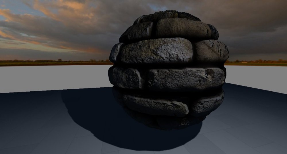
Here is the result:
Surface displacement takes the object scale into account, so if you scale up an object the displacement will increase accordingly.
Surface Curvature
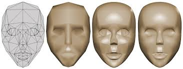
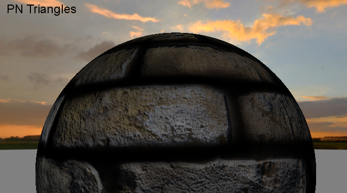
I also added an implementation of the PN Triangles technique. This treats a triangle as control points for a Bezier curve and projects tessellated curved surfaces outwards.
You can see below the shot using the PN Triangles technique eliminates the pointy edges of the sphere.
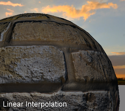
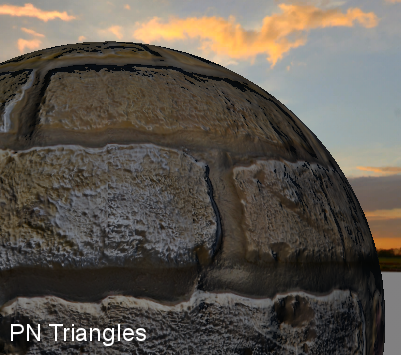
The effects is good, although it is more computationally expensive, and if a strong displacement map is in use, you can't really see a difference. Since vertex positions are being changed but texture coordinates are still using the same interpolation function, it can make texture coordinates appear distorted. To counter this, texture coordinates would need to be recalculated from the new vertex positions.
EDIT:
I found a better algorithm that doesn't produce the texcoord errors seen above.
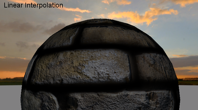
Finally, a global tessellation factor has been added that lets you scale the effect for different hardware levels:
void SetTessellationDetail(const float detail)
The default setting is 1.0, so you can use this to scale up or down the detail any way you like.
-
 2
2



5 Comments
Recommended Comments